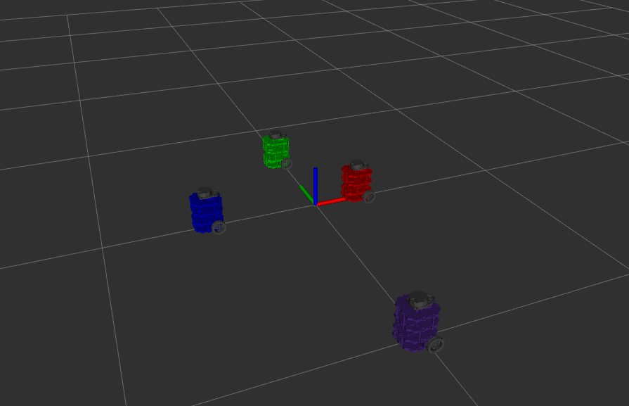
实机演示
机器人沿环形路线行驶并返回起始位置。绿色机器人为 SLAM 估计,蓝色机器人为原始里程计。
概述
本项目为西北大学 ME495《机器人感知、导航与机器学习》课程作业(2025年冬季学期),在真实 TurtleBot3 上实现了完整的 EKF SLAM 管线,包含路标检测、里程计与双机 ROS 2 通信架构。
核心成果:
| 对比 | x 误差 (m) | y 误差 (m) | 总误差 (m) |
|---|---|---|---|
| 真实值 vs 里程计 | 0.633 | 0.176 | 0.657 |
| 真实值 vs SLAM | 0.001 | 0.000 | 0.001 |
SLAM 将位置误差从里程计的 65.7 cm 降低至 1 mm,提升幅度达 657 倍。
工作原理
系统将里程计与 LiDAR 路标观测融合,在机器人运动过程中同时估计机器人位姿和路标位置。
路标检测:LiDAR 点云聚类与圆拟合
LiDAR 扫描数据经过处理,识别出场景中的圆柱形路标:
- 聚类:将角度间距超过阈值的相邻扫描点分入不同的聚类
- 圆拟合:对每个聚类应用 Umeyama 圆拟合算法,估计圆心坐标 $(x_c, y_c)$ 和半径 $r$
- 过滤:根据半径范围和聚类大小剔除误检(如墙面反射)
经过拟合的圆心坐标即为路标的相对位置,直接输入 EKF 更新步骤。
扩展卡尔曼滤波器(EKF)
EKF 维护联合状态向量 $\mathbf{x} = [q^T, m^T]^T$,其中 $q = (\theta, x, y)$ 为机器人位姿,$m$ 为路标坐标列表。
预测步骤(利用里程计):
$$\hat{x}_{t|t-1} = f(\hat{x}_{t-1|t-1}, u_t)$$ $$\Sigma_{t|t-1} = F_t \Sigma_{t-1|t-1} F_t^T + Q_t$$更新步骤(利用路标观测):
$$K_t = \Sigma_{t|t-1} H_t^T (H_t \Sigma_{t|t-1} H_t^T + R_t)^{-1}$$ $$\hat{x}_{t|t} = \hat{x}_{t|t-1} + K_t (z_t - h(\hat{x}_{t|t-1}))$$ $$\Sigma_{t|t} = (I - K_t H_t) \Sigma_{t|t-1}$$未知数据关联
每次观测到路标时,系统必须判断它是已知路标还是新路标。本项目使用马氏距离进行匹配:
$$d_i = (z - \hat{z}_i)^T (H_i \Sigma H_i^T + R)^{-1} (z - \hat{z}_i)$$若最小马氏距离低于阈值,则将观测值与对应路标关联;否则,将其初始化为新路标加入地图。这使系统在无需预先知晓路标数量和位置的情况下正常运行。
仿真
已知数据关联(仿真)
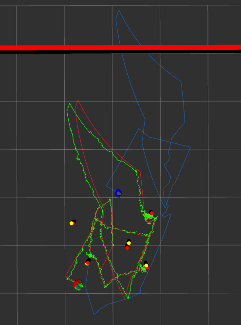
图中各颜色含义:
- 红色:真实轨迹(ground truth)
- 绿色:SLAM 估计轨迹
- 蓝色:原始里程计轨迹
- 黄色圆圈:真实路标位置
- 红色圆圈:SLAM 估计的路标位置
未知数据关联(仿真)
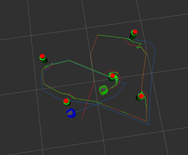
仿真在带有可配置墙壁和圆柱障碍物的 nusim 虚拟环境中运行,同时发布带噪声的编码器数据和虚假 LiDAR 扫描。
系统架构
双机 ROS 2 部署
系统分布在两台机器上运行:
TurtleBot3(机载)                     PC(远程)
├── 硬件驱动                           ├── EKF SLAM 节点
├── 路标检测(圆拟合)                  ├── RViz 可视化
└── wheel_cmd / joint_states           └── 全局位姿估计
         └────────── WiFi ──────────────┘
TurtleBot 端:
ros2 launch nuslam turtlebot_bringup.launch.xml
PC 端:
ros2 launch nuslam pc_bringup.launch.xml
软件包结构
| 软件包 | 功能 |
|---|---|
| nuslam | EKF SLAM 核心,路标检测,数据关联 |
| nuturtle_control | TurtleBot3 硬件接口,里程计,轨迹控制 |
| nusim | 仿真环境,噪声模型,虚假 LiDAR |
| nuturtle_description | URDF,TF 树,多机器人可视化 |
| turtlelib | C++ 几何库:SE(2) 变换,差速驱动运动学 |
turtlelib:核心几何库
turtlelib 是贯穿整个系统的自定义 C++ 库,提供:
- SE(2) 刚体变换:旋转矩阵、平移向量的复合与求逆
- Twist/Wrench 运算:速度旋量在不同坐标系间的转换
- 差速驱动运动学:正向/逆向运动学,轮速到机体速度的映射
硬件
| 组件 | 型号 |
|---|---|
| 移动平台 | TurtleBot3 Burger |
| 处理器 | Raspberry Pi(机载) |
| LiDAR | 360° 2D 激光雷达 |
| 通信 | WiFi(机器人 ↔ PC) |
软件技术栈
| 层级 | 技术 |
|---|---|
| 操作系统 | Linux |
| 机器人框架 | ROS 2 |
| 语言 | C++17 |
| 状态估计 | 自定义 EKF(Eigen) |
| 路标检测 | Umeyama 圆拟合 |
| 数据关联 | 马氏距离 |
| 可视化 | RViz2 |
致谢
本项目为西北大学 ME495《机器人感知、导航与机器学习》课程的期末作业,由 Matthew Elwin 教授授课。课程提供了完成本项目所必需的理论基础与硬件平台支持。
Real Robot Demo
The robot drives a circuit and returns to its starting position. The green robot is the SLAM estimate, the blue robot is raw odometry.
Overview
This project, built for Northwestern University’s ME495 Sensing, Navigation and Machine Learning for Robotics (Winter 2025), implements a full EKF SLAM pipeline on a real TurtleBot3 — including landmark detection, odometry, and a two-machine ROS 2 architecture.
Key Results:
| Comparison | x error (m) | y error (m) | Total (m) |
|---|---|---|---|
| Actual vs Odometry | 0.633 | 0.176 | 0.657 |
| Actual vs SLAM | 0.001 | 0.000 | 0.001 |
SLAM reduces position error from 65.7 cm (odometry) to 1 mm — a 657× improvement.
How It Works
The system fuses odometry with LiDAR landmark observations to simultaneously estimate the robot’s pose and landmark positions as it drives.
Landmark Detection: LiDAR Clustering and Circle Fitting
LiDAR scan data is processed to identify cylindrical landmarks in the environment:
- Clustering: Adjacent scan points separated by more than an angular gap threshold are split into different clusters
- Circle fitting: Umeyama circle fitting is applied to each cluster to estimate center $(x_c, y_c)$ and radius $r$
- Filtering: Clusters with radii or sizes outside expected ranges are rejected (e.g., wall reflections)
The fitted circle centers provide relative landmark positions, which feed directly into the EKF update step.
Extended Kalman Filter (EKF)
The EKF maintains a joint state vector $\mathbf{x} = [q^T, m^T]^T$, where $q = (\theta, x, y)$ is the robot pose and $m$ is the list of landmark coordinates.
Prediction step (using odometry):
$$\hat{x}_{t|t-1} = f(\hat{x}_{t-1|t-1}, u_t)$$ $$\Sigma_{t|t-1} = F_t \Sigma_{t-1|t-1} F_t^T + Q_t$$Update step (using landmark observations):
$$K_t = \Sigma_{t|t-1} H_t^T (H_t \Sigma_{t|t-1} H_t^T + R_t)^{-1}$$ $$\hat{x}_{t|t} = \hat{x}_{t|t-1} + K_t (z_t - h(\hat{x}_{t|t-1}))$$ $$\Sigma_{t|t} = (I - K_t H_t) \Sigma_{t|t-1}$$Unknown Data Association
Every time a landmark is observed, the system must decide whether it matches a known landmark or is new. This project uses Mahalanobis distance for matching:
$$d_i = (z - \hat{z}_i)^T (H_i \Sigma H_i^T + R)^{-1} (z - \hat{z}_i)$$If the minimum Mahalanobis distance falls below a threshold, the observation is associated with that landmark. Otherwise, it is initialized as a new landmark and added to the map. This allows the system to operate without knowing the number or positions of landmarks in advance.
Simulation
Known Data Association (Simulation)
Color coding:
- Red: Ground truth trajectory
- Green: SLAM estimated trajectory
- Blue: Raw odometry trajectory
- Yellow circles: True landmark positions
- Red circles: SLAM-estimated landmark positions
Unknown Data Association (Simulation)
Simulation runs in the nusim virtual environment with configurable walls and cylindrical obstacles, publishing noisy encoder data and a fake LiDAR scan.
System Architecture
Two-Machine ROS 2 Deployment
The system runs distributed across two machines:
TurtleBot3 (onboard)                   PC (remote)
├── Hardware drivers                   ├── EKF SLAM node
├── Landmark detection (circle fit)    ├── RViz visualization
└── wheel_cmd / joint_states           └── Global pose estimate
         └──────── WiFi ────────────────┘
On the TurtleBot:
ros2 launch nuslam turtlebot_bringup.launch.xml
On the PC:
ros2 launch nuslam pc_bringup.launch.xml
Package Structure
| Package | Role |
|---|---|
| nuslam | EKF SLAM core, landmark detection, data association |
| nuturtle_control | TurtleBot3 hardware interface, odometry, trajectory control |
| nusim | Simulation environment, noise models, fake LiDAR |
| nuturtle_description | URDF, TF tree, multi-robot visualization |
| turtlelib | C++ geometry library: SE(2) transforms, differential drive kinematics |
turtlelib: Core Geometry Library
turtlelib is a custom C++ library used throughout the system, providing:
- SE(2) rigid body transforms: Composition and inversion of rotation matrices and translation vectors
- Twist/Wrench operations: Transformation of velocity twists between frames
- Differential drive kinematics: Forward/inverse kinematics, wheel speed to body velocity mapping
Hardware
| Component | Model |
|---|---|
| Mobile platform | TurtleBot3 Burger |
| Processor | Raspberry Pi (onboard) |
| LiDAR | 360° 2D laser scanner |
| Communication | WiFi (robot ↔ PC) |
Software Stack
| Layer | Technology |
|---|---|
| OS | Linux |
| Robotics Framework | ROS 2 |
| Language | C++17 |
| State Estimation | Custom EKF (Eigen) |
| Landmark Detection | Umeyama circle fitting |
| Data Association | Mahalanobis distance |
| Visualization | RViz2 |
Acknowledgement
This project was completed as the final assignment for ME495 Sensing, Navigation and Machine Learning for Robotics at Northwestern University, under the instruction of Professor Matthew Elwin. The course provided the foundational framework and hardware infrastructure that made this work possible.