灵感来源
记得五岁那年第一次看《机器人总动员》。在一个场景中,伊娃处于休眠模式,但她依然悬停着。瓦力用绳子拖着她到处走,她就那样丝滑地跟随着。完全顺应外力,显得很轻松。
那个画面给当时的我留下了深刻的印象。于是这个项目我就试图打造出同样特质的东西:一架能感知施加在它身上的力并与你同行的无人机。当然这样还不够有趣,我要让它可以不是简单地跟随,而是以一种聪明的方式———遇到障碍的时候要抵抗,或者丝滑地绕过去。
概述
一架可沿施加外力方向移动的四旋翼无人机 —— 拖动它,它就会跟随。 卡尔曼滤波器仅从位置观测中估计外力,基于 LiDAR 的人工势场在保持预期运动方向的同时防止碰撞。
行为模式:
- 无输入时原地悬停
- 沿施力方向以与力大小成正比的速度移动
- 外力释放后减速并保持位置
- 使用 2D LiDAR 对附近障碍物产生排斥力(定向半圆 + 全向安全包络)
演示
力柔顺 + 避障
仅力柔顺
工作原理
无外力施加时,无人机保持静止。沿任意水平方向拖动它,它将沿该方向加速,速度与力的大小成正比。松开后,它减速至位置保持状态。启用避障功能时,飞行员持续沿期望方向施力,无人机则会自动绕过障碍物飞行。
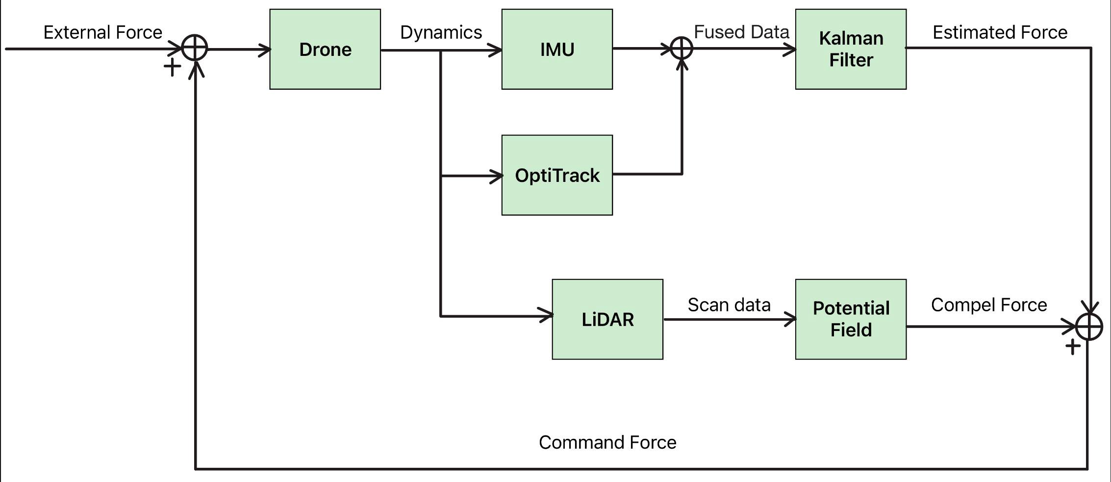
上图展示了完整的系统架构:OptiTrack 位置观测输入卡尔曼滤波器以估计外力,估计的外力与 LiDAR 产生的避障斥力叠加后,转换为速度指令发送至 PX4。
数学模型
力分解
一架倾斜的四旋翼如果没有水平加速度,则必然受到外部水平力的作用。这是使无传感器力估计(Sensorless Force Estimation)成为可能的核心洞察。
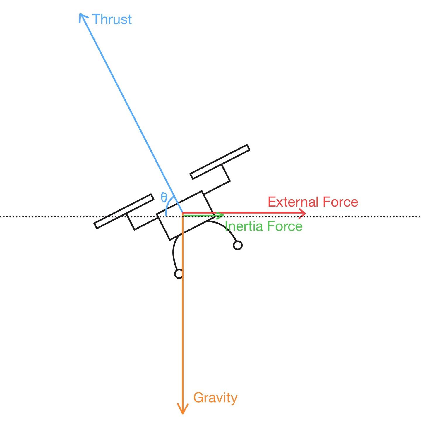
在准稳态下,力平衡方程为:
- 垂直方向: $T\sin(\theta) = G$ —— 垂直拉力等于重力
- 水平方向: $T\cos(\theta) = ma + E$ —— 水平拉力克服惯性和外力 $E$
通过 OptiTrack 观测位置并已知拉力指令,任何残余水平加速度都可归因于外力。
坐标系约定
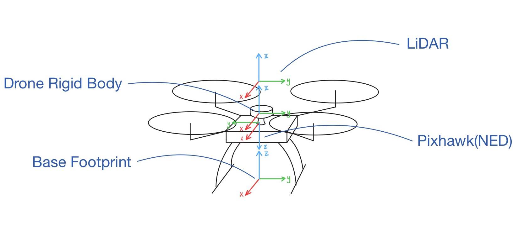
系统使用四个坐标系,均可在实物无人机上辨识:
| 坐标系 | 约定 | 作用 |
|---|---|---|
| Pixhawk | NED(北-东-地) —— X=北, Y=东, Z=下 | PX4 内部状态,轨迹设定值 |
机体刚体 (imu_link) | FLU(前-左-上) —— X=前, Y=左, Z=上 | OptiTrack 跟踪坐标系;卡尔曼滤波器位置观测 |
| base_footprint | FLU —— X=前, Y=左, Z=上 | TF 树中地面投影的机体位姿 |
LiDAR (laser) | FLU —— X=前, Y=左, Z=上 | 2D 扫描坐标系;与机体刚性对齐(无旋转) |
所有 ROS 坐标系使用 FLU。仅 Pixhawk 使用 NED。转换链(机体 FLU → NED),利用偏航角 $\psi$:
$$x_{ned} = \cos(\psi) x_{frd} + \sin(\psi) y_{frd}$$ $$y_{ned} = -\sin(\psi) x_{frd} + \cos(\psi) y_{frd}$$其中 $x_{frd} = x_{flu}$, $y_{frd} = -y_{flu}$。
姿态编码水平力
由于 PX4 通过倾斜无人机来产生水平运动,俯仰角和横滚角是水平力的直接观测量。这验证了模型的正确性,并为在卡尔曼滤波器的控制输入项中使用姿态角提供了依据。
俯仰角与 X 轴位置误差(NED)的相关性:
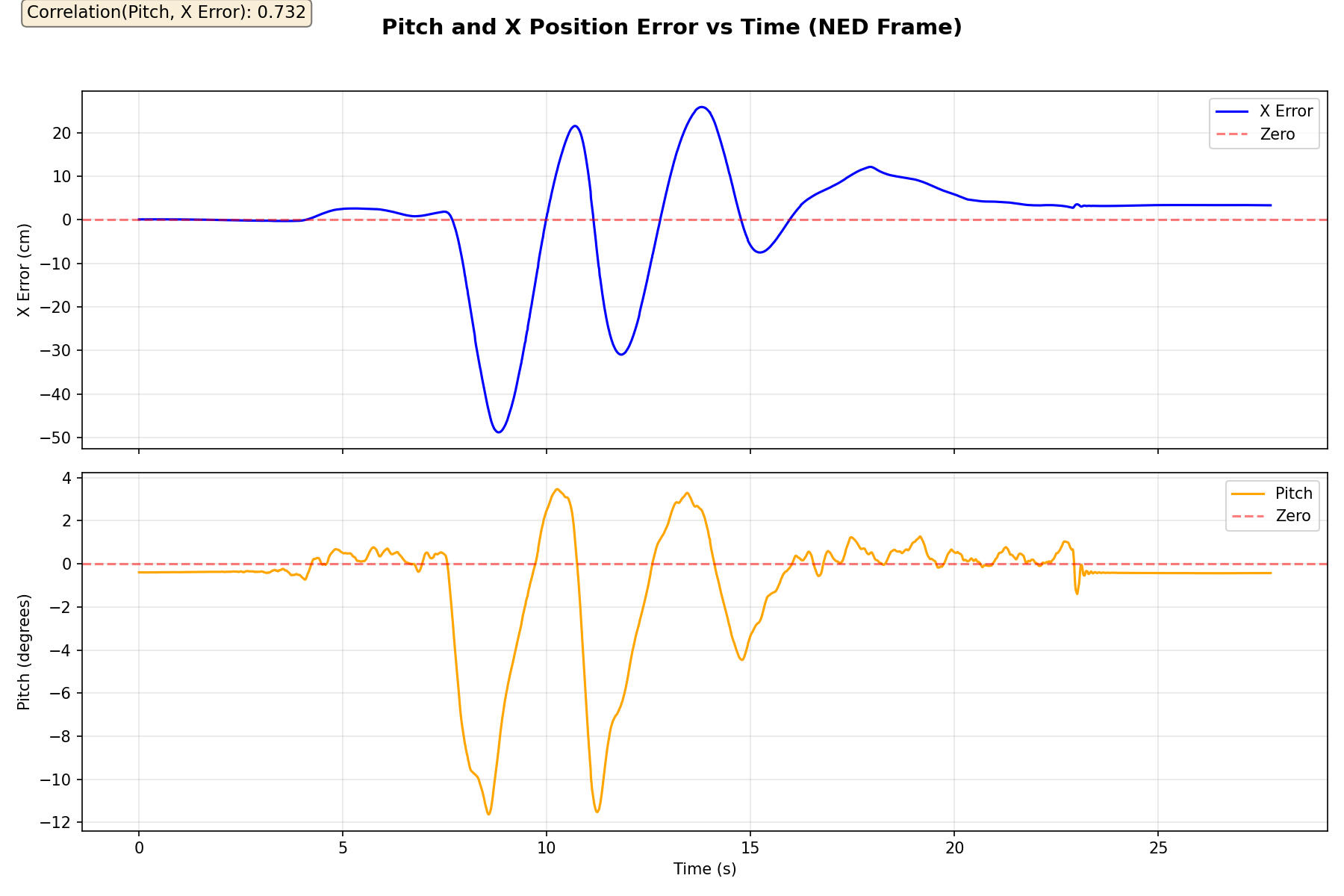
相关系数 = 0.732。俯仰角追踪 X 轴误差,验证了模型:当无人机被向前拖动时,PX4 使机头下俯以产生加速度,造成位置误差不断增大,直至匹配指令速度。
横滚角与 Y 轴位置误差(NED)的相关性:
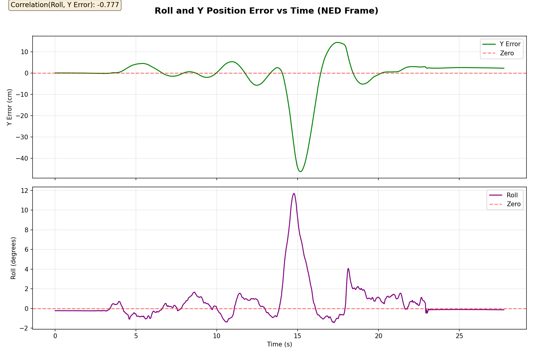
相关系数 = −0.777(负号源于 FRD→NED 的符号约定)。横滚角追踪 Y 轴误差且符号翻转与预期一致,符合坐标系旋转关系。
卡尔曼滤波力估计器
卡尔曼滤波器在 NED 世界坐标系中以 50 Hz 频率估计 $[p_x, v_x, p_y, v_y, F_x, F_y]$,仅使用 OptiTrack 位置观测。
状态转移:
$$p_x \leftarrow p_x + v_x \Delta t$$ $$v_x \leftarrow v_x + (F_x/m)\Delta t + Bu_x$$ $$F_x \leftarrow F_x \quad \text{(建模为随机游走)}$$($y$ 方向对称。)
控制输入 $Bu$ —— 考虑完整横滚/俯仰/偏航旋转后,拉力产生的 NED 水平加速度:
$$Bu_x = -(T/m)[\cos(\psi)\sin(\theta)\cos(\phi) + \sin(\psi)\sin(\phi)]\,\Delta t$$ $$Bu_y = -(T/m)[\sin(\psi)\sin(\theta)\cos(\phi) - \cos(\psi)\sin(\phi)]\,\Delta t$$拉力大小:$T = mg / (\cos(\phi)\cos(\theta))$,因此无论倾斜角度如何,垂直分量始终等于重力。
观测量: OptiTrack 2D 位置 $[p_x, p_y]$。滤波器从悬停状态约 1 秒内收敛,并持续跟踪缓慢变化的外力。
估计的 $[F_x, F_y]$ 驱动速度设定值。障碍物排斥力在估计之后叠加到 $F_{cmd}$ 上,不会反馈到卡尔曼滤波器中。
避障
RPLidar 扫描产生的斥力通过人工势场方法叠加在估计的外力上。
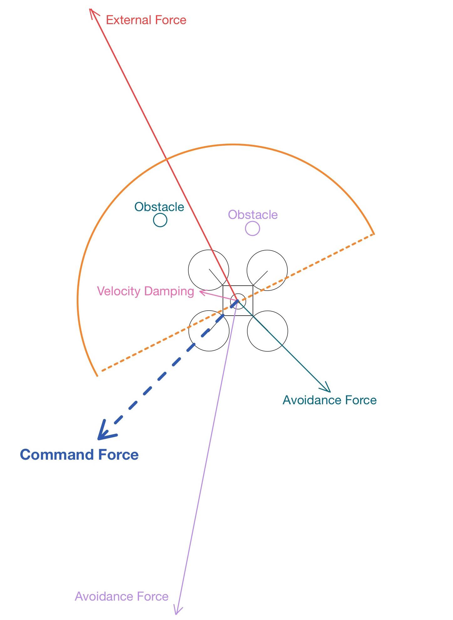
上图展示了完整的力叠加关系:橙色弧线是面向 $F_{ext}$(红色)的半圆检测区域。区域内的障碍物产生避障力(青色和紫色箭头)将无人机推离。速度阻尼(粉色)在斥力激活时抵消当前速度。指令力(蓝色虚线)是所有分量的矢量和。
两遍扫描处理
第一遍 —— 半圆(定向): 在 $F_{ext}$(橙色弧线)方向的 ±90° 锥形区域内扫描,扫描半径随力的大小缩放。确保预期运动方向上的障碍物被提前检测到。
第二遍 —— 全向安全包络: 在固定近距半径(默认 0.5 m)内进行 360° 全方位扫描。当无人机为避开前方障碍物而侧移时,捕捉侧方和后方障碍物 —— 防止盲区碰撞。
两遍扫描的结果累加到同一斥力向量中。在无人机附近的重叠区域产生更强的斥力,恰好在最需要的地方。
力的叠加
$$F_{cmd} = F_{ext} + F_{rep} + F_{damp}$$- $F_{ext}$ —— 卡尔曼滤波器估计的外力
- $F_{rep} = \sum k/d^2$ 指向无人机方向,来自所有检测到的障碍物(限幅至
max_repulsion_force) - $F_{damp} = -\text{damping} \times (|F_{rep}| / F_{rep,max}) \times v_{cmd}$ —— 抵消速度,随无人机进入斥力场而成比例增长
硬件平台
| 组件 | 型号 | 作用 |
|---|---|---|
| 机架 | Holybro X500 V2 | 四旋翼平台 |
| 飞行控制器 | Pixhawk 6C | PX4 自动驾驶仪,姿态和速率控制 |
| 机载电脑 | Raspberry Pi 5(树莓派 5) | uXRCE-DDS 桥接,通过 UART 通信 |
| 动作捕捉 | OptiTrack | 120 Hz 六自由度位置 |
| LiDAR | SLAMTEC RPLidar(思岚激光雷达) | 2D 扫描,360°,约 8 m 范围 |
通信链路:
OptiTrack → 笔记本电脑 (ROS 2) ──WiFi──► 树莓派 ──UART (921600 波特率)──► Pixhawk (PX4)
软件技术栈
| 层级 | 技术 |
|---|---|
| 操作系统 | Ubuntu 24.04(树莓派)、Linux(笔记本电脑) |
| ROS 2 | Jazzy(树莓派)、Kilted(笔记本电脑) |
| 自动驾驶仪 | PX4 |
| DDS 桥接 | uXRCE-DDS Agent |
| 定位 | OptiTrack Motive + TF2 |
| 力估计器 | 自定义卡尔曼滤波器(Eigen),ROS 2 节点 |
| 避障 | 基于 LaserScan 的人工势场 |
Inspiration
When I was five, I watched WALL-E. In this scene, EVE is in sleep mode – but she’s still hovering. WALL-E pulls her along with a string, and she just… follows. Fully compliant, effortless.
That image has stayed with me ever since. This project is my attempt to build something with that same quality: a quadrotor that senses the force applied to it and moves with you. Besides, I want the quadrotor to follow smartly–it should repel or bypass when it detects obstacles in the front.
Overview
A quadrotor that moves in the direction of applied external force – pull it, and it follows. A Kalman filter estimates external force from position observations alone, while a LiDAR-based potential field prevents collisions while preserving intended motion direction.
Behavior Modes:
- Hovers in place with no input
- Moves in the direction of applied force at a speed proportional to force magnitude
- Decelerates and holds position when force is released
- Uses 2D LiDAR to generate repulsive forces from nearby obstacles (directional hemicircle + omnidirectional safety bubble)
Demo
Force Compliance + Obstacle Avoidance
Force Compliance Only
How It Works
With no external force, the quadrotor stays still. Pull it in any horizontal direction, and it accelerates that way at a speed proportional to the force magnitude. Release it, and it decelerates to a position hold. With obstacle avoidance enabled, the pilot applies sustained force in the desired direction, and the quadrotor automatically navigates around obstacles.
The diagram above shows the full system architecture: OptiTrack position measurements feed into the Kalman filter to estimate external force, which is then combined with LiDAR-generated repulsive forces and converted into velocity setpoints sent to PX4.
Mathematical Model
Force Decomposition
A tilted quadrotor with no horizontal acceleration must be subject to an external horizontal force. This is the core insight that makes sensorless force estimation possible.
At quasi-steady-state, the force balance equations are:
- Vertical: $T\sin(\theta) = G$ – vertical thrust equals gravity
- Horizontal: $T\cos(\theta) = ma + E$ – horizontal thrust overcomes inertia and external force $E$
By observing position via OptiTrack and knowing the thrust command, any residual horizontal acceleration can be attributed to external force.
Coordinate Frame Convention
The system uses four coordinate frames, all identifiable on the physical quadrotor:
| Frame | Convention | Purpose |
|---|---|---|
| Pixhawk | NED (North-East-Down) – X=North, Y=East, Z=Down | PX4 internal state, trajectory setpoints |
Body rigid (imu_link) | FLU (Forward-Left-Up) – X=Fwd, Y=Left, Z=Up | OptiTrack tracking frame; KF position observations |
| base_footprint | FLU – X=Fwd, Y=Left, Z=Up | Ground-projected body pose in TF tree |
LiDAR (laser) | FLU – X=Fwd, Y=Left, Z=Up | 2D scan frame; rigidly aligned with body (no rotation) |
All ROS frames use FLU. Only Pixhawk uses NED. The conversion chain (body FLU → NED), using yaw angle $\psi$:
$$x_{ned} = \cos(\psi) x_{frd} + \sin(\psi) y_{frd}$$ $$y_{ned} = -\sin(\psi) x_{frd} + \cos(\psi) y_{frd}$$where $x_{frd} = x_{flu}$, $y_{frd} = -y_{flu}$.
Attitude Encodes Horizontal Force
Since PX4 tilts the quadrotor to produce horizontal motion, pitch and roll angles are direct observations of horizontal force. This validates the model and justifies using attitude angles in the Kalman filter’s control input term.
Pitch vs X-axis Position Error (NED):
Correlation = 0.732. Pitch tracks X-axis error, validating the model: when the quadrotor is pulled forward, PX4 pitches nose-down to generate acceleration, causing position error to grow until the commanded velocity is matched.
Roll vs Y-axis Position Error (NED):
Correlation = −0.777 (negative sign due to FRD→NED sign convention). Roll tracks Y-axis error with flipped sign as expected, consistent with the coordinate frame rotation.
Kalman Filter Force Estimator
The Kalman filter estimates $[p_x, v_x, p_y, v_y, F_x, F_y]$ in the NED world frame at 50 Hz, using only OptiTrack position observations.
State Transition:
$$p_x \leftarrow p_x + v_x \Delta t$$ $$v_x \leftarrow v_x + (F_x/m)\Delta t + Bu_x$$ $$F_x \leftarrow F_x \quad \text{(modeled as random walk)}$$($y$-direction is symmetric.)
Control Input $Bu$ – NED horizontal acceleration from thrust after full roll/pitch/yaw rotation:
$$Bu_x = -(T/m)[\cos(\psi)\sin(\theta)\cos(\phi) + \sin(\psi)\sin(\phi)]\,\Delta t$$ $$Bu_y = -(T/m)[\sin(\psi)\sin(\theta)\cos(\phi) - \cos(\psi)\sin(\phi)]\,\Delta t$$Thrust magnitude: $T = mg / (\cos(\phi)\cos(\theta))$, so the vertical component always equals gravity regardless of tilt.
Observations: OptiTrack 2D position $[p_x, p_y]$. The filter converges from hover in ~1 second and continuously tracks slowly varying external forces.
The estimated $[F_x, F_y]$ drives velocity setpoints. Obstacle repulsive forces are added to $F_{cmd}$ after estimation and do not feed back into the Kalman filter.
Obstacle Avoidance
Repulsive forces from RPLidar scans are superimposed on the estimated external force via the potential field method.
The figure above shows the full force superposition: the orange arc is the hemicircle detection zone facing $F_{ext}$ (red). Obstacles within the zone generate avoidance forces (cyan and purple arrows) pushing the quadrotor away. Velocity damping (pink) counteracts current velocity when repulsive forces activate. The command force (blue dashed) is the vector sum of all components.
Two-Pass Scan Processing
Pass 1 – Hemicircle (Directional): Scans within a ±90° cone in the direction of $F_{ext}$ (orange arc), with scan radius scaling with force magnitude. Ensures obstacles in the intended motion direction are detected early.
Pass 2 – Omnidirectional Safety Bubble: Performs a 360° scan within a fixed close-range radius (default 0.5 m). Catches side and rear obstacles when the quadrotor sidesteps to avoid frontal obstacles – prevents blind-spot collisions.
Results from both passes accumulate into the same repulsive force vector. Overlapping zones near the quadrotor produce stronger repulsion, exactly where it’s needed most.
Force Superposition
$$F_{cmd} = F_{ext} + F_{rep} + F_{damp}$$- $F_{ext}$ – Kalman filter estimated external force
- $F_{rep} = \sum k/d^2$ pointing toward the quadrotor from all detected obstacles (clamped to
max_repulsion_force) - $F_{damp} = -\text{damping} \times (|F_{rep}| / F_{rep,max}) \times v_{cmd}$ – counteracts velocity, scaling proportionally as the quadrotor enters the repulsive field
Hardware
| Component | Model | Purpose |
|---|---|---|
| Frame | Holybro X500 V2 | Quadrotor platform |
| Flight Controller | Pixhawk 6C | PX4 autopilot, attitude and rate control |
| Companion Computer | Raspberry Pi 5 | uXRCE-DDS bridge, UART communication |
| Motion Capture | OptiTrack | 120 Hz 6-DOF position |
| LiDAR | SLAMTEC RPLidar | 2D scan, 360°, ~8 m range |
Communication Link:
OptiTrack → Laptop (ROS 2) ──WiFi──► Raspberry Pi ──UART (921600 baud)──► Pixhawk (PX4)
Software Stack
| Layer | Technology |
|---|---|
| OS | Ubuntu 24.04 (Raspberry Pi), Linux (Laptop) |
| ROS 2 | Jazzy (Raspberry Pi), Kilted (Laptop) |
| Autopilot | PX4 |
| DDS Bridge | uXRCE-DDS Agent |
| Localization | OptiTrack Motive + TF2 |
| Force Estimator | Custom Kalman filter (Eigen), ROS 2 node |
| Obstacle Avoidance | LaserScan-based potential field |